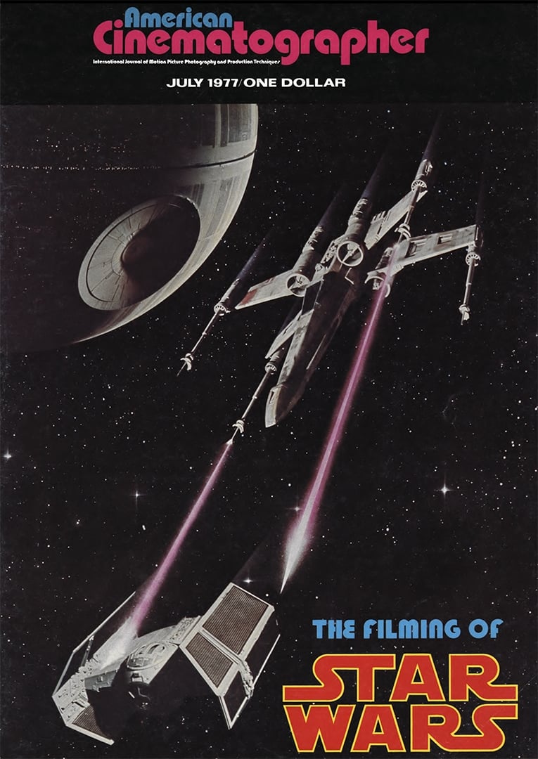
Star Wars: Miniature and Mechanical Special Effects
Detailing the intricate production of the film’s visual effects, utilizing a novel motion-control camera system.
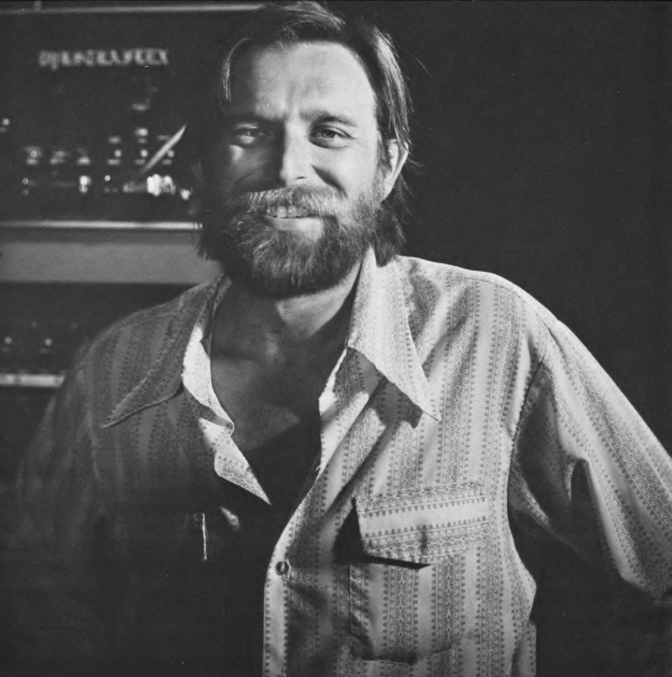
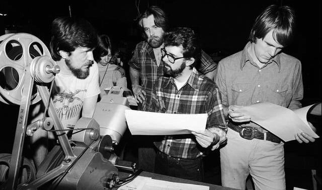
By John Dykstra
Special Photographic Effects Supervisor
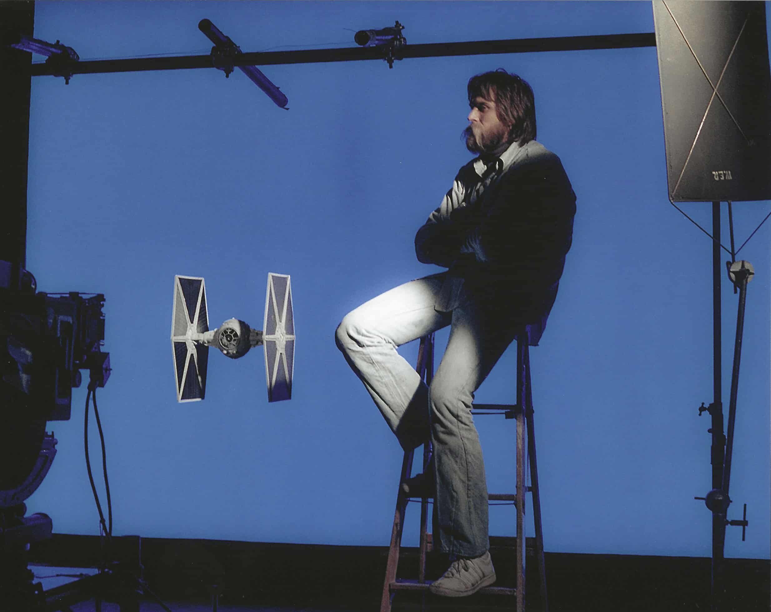
In June of 1975, I was contacted by George Lucas and Gary Kurtz with regard to my supervising the photographic special effects for Star Wars. These first meetings with George and Gary outlined effects scenes that involved spacecraft engaged in acrobatics that any stunt pilot would be proud of: Three or four ships performing rolls or loops while firing lasers at each other in the classic “dog fight” tradition. All this was to occur while being viewed from a camera platform that itself needed the fluidity and freedom of motion of a camera plane. This visual concept was a far cry from the locked-off camera approach to spacecraft miniature photography seen in the space classics of the past. This was a challenge, to say the least.
As the meetings and story breakdown continued, it became clear that this film would not showcase 20 or 30 special photographic effects shots, but would use spaceships, miniatures, and all manner of photographic effects, as you would use automobiles in a film of contemporary time setting. In the entire film there are some 365 miniature and photographic effects shots. The challenge, therefore, became a task of mammoth proportions.
In order to produce the quantity and quality of special photographic effects shots called for in Star Wars, a complete in-house system would have to be developed. This system would include miniature design and construction facilities; the design and fabrication of a camera motion control system; electronics and mechanical facets, and a complete optical house and animation department. I felt that the in-house system would be the only way that consistency of quality and control over each of the separate operations could be maintained.
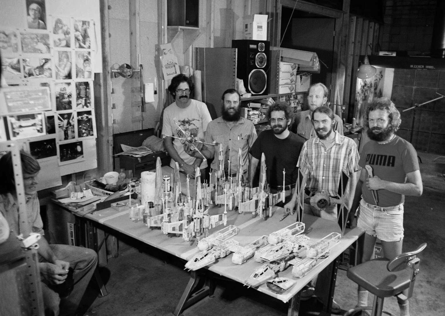
First, I sought out the personnel that I felt were necessary to carry out the special requirements of this project. This included conceptualization, design, and execution of the visuals and of the equipment used to produce those visuals. The electronics portion of the system would be handled by Al Miller Electronics. Al and I had worked together in the past and already had a basic design for the electronics/camera system worked out, and now we had an application for this system. For the mechanical aspects of this project, I contacted Don Trumbull, Richard Alexander and Bill Shourt. All three had talents in design and manufacture of one or two off-types of machines this project would require. In order to make certain that the people who would have to use the equipment had a hand in its design, I brought in Richard Edlund to be the director of photography. Grant McCune was given the responsibility of producing our miniatures. A production shop was set up by Bob Shepard, and all scheduling and co-ordination of special effects shots was done by George Mather.
In eight months we brought the facility in Van Nuys, California, from an empty warehouse to an incredibly versatile system. The talent and integrity of these people, plus our ability to communicate with each other, provided the key to the success of the system.
As the equipment began to evolve, the basic in-house departments began to form. Robbie Blalack (Praxis) began setting up an optical department. Adam Beckett began designing lasers and other animation which would be used in Star Wars. Mary Lind set up a film control room to handle each shot, as it traveled from camera on stage through rotoscope, and optical.
Because the photographic effects were to be done in the United States, and the live-action filming was to be done in England, some rather severe communication problems had to be overcome. George Lucas, Joe Johnston and myself described each shot in one or more storyboards, and its requirements were established, right to the frame count. Most of this information came from a cut battle sequence, made up of excerpts from war movies. This established the size and speed of the fighters and their positions in frame. With this first set of storyboards in hand, we set about finalizing our miniatures, and photographic systems.
The format of the system was first to be considered. Star Wars was to be released in the wide (2.40: 1) format. The problems presented by trying to produce the incredibly complex photographic effects in this anamorphic format were staggering. There were problems of depth of field and image quality after numerous optical steps, hyperfocal distance of the anamorphic lenses, and complex articulate rotoscope work in a squeezed format. To eliminate the majority of these difficulties, it was decided that a spherical optic was necessary for our effects work. But we still had the problem of image degradation due to optical dupe steps. Once we had filmed the foreground elements and matched move backgrounds, these elements would then have to be combined in composite. The logical solution was to increase the negative size. Rather than use 65mm with its inherent processing and emulsion availability problems, we chose to use the horizontal 8-perf 35mm format similar to VistaVision. This not only gave us additional negative area, but also all of the advantages of high-quality spherical optics produced for conventional SLR still cameras with their incredible lens variety.
One of the problems that the 8-perf format presented was optical combination. I decided that in-house opticals were a must in order to maintain our approach. We acquired an 8-perf printer (non-operative) and converted it to our electronics-control approach. A second printer was made available to use. It was also converted to electronic control, and 4/8 perf operation. Due to the 8-perf horizontal format, we had to have lenses designed and constructed for the aerial position of our two-head printers, optimizing the image quality from the aerial head and making the printer considerably more flexible. With this choice, we had all the emulsions and processing available to conventional 4-perf production and a larger negative area.
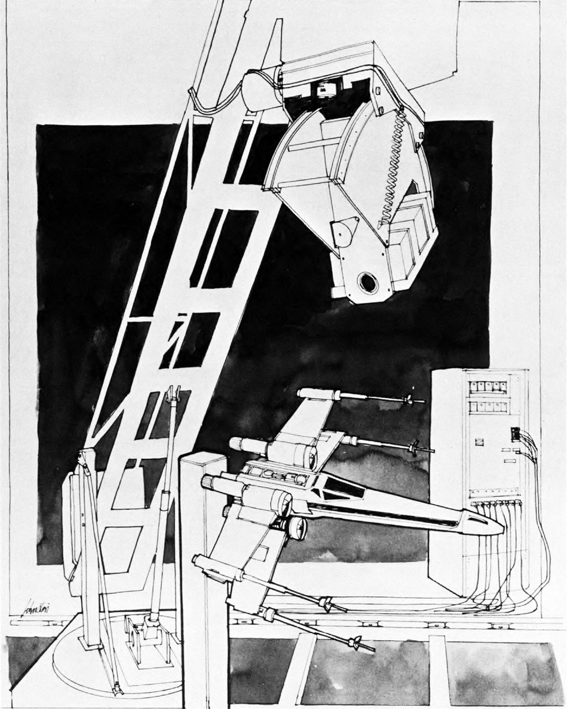
Concurrent with the assembly of the optical department and model facilities we continued the development of the photographic and motion control systems. Having completed the design in July of 1975, we began construction of the "Dykstraflex" described as follows:
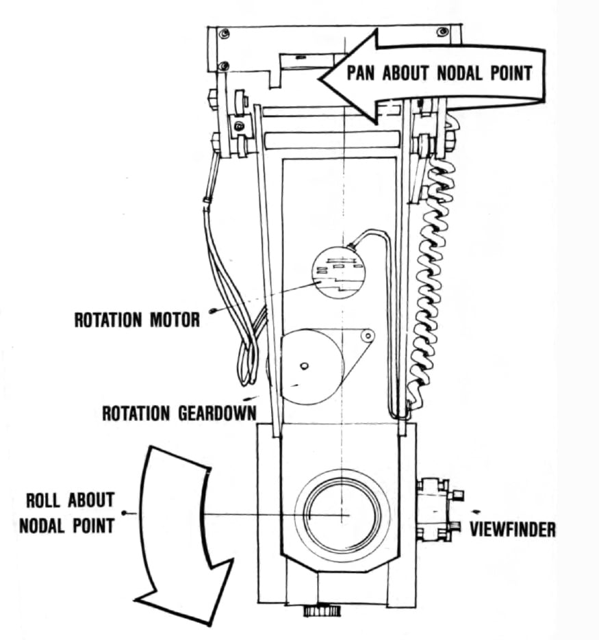
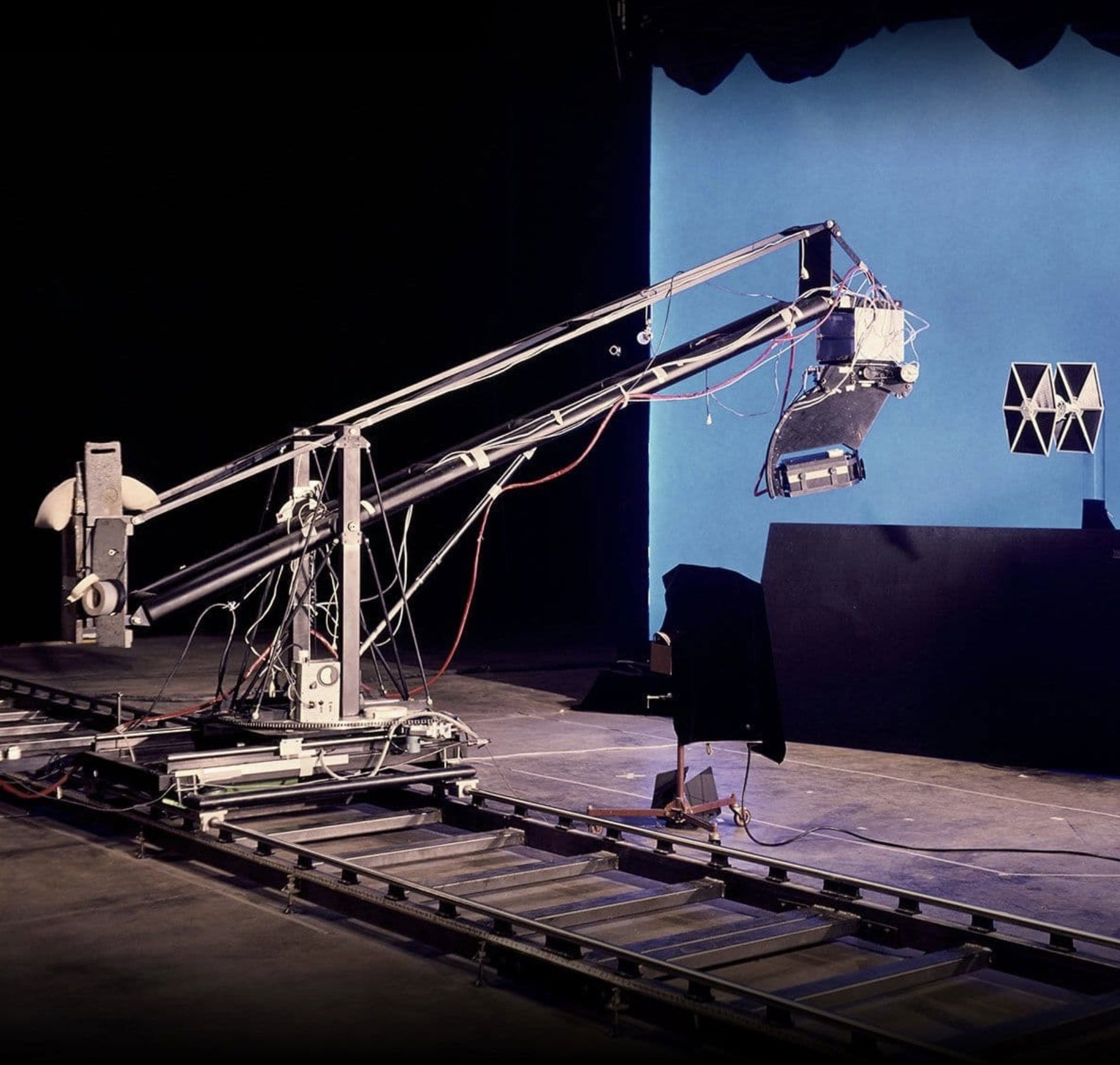
A system using stepping motors for control of any motion in the camera/subject positional relationship. These motors drive a track boom system with seven axes of motion and very precise tolerances. By using the camera frame rate and count as a time base, we can record camera/subject positional changes at 24 frames-per-second. The positional change is viewed through the taking lens and is controlled by a joy stick for multi-axes moves or by an individual potentiometer for single-axis moves.
If one axis, or more, of the move requires modification, we then go back and rerecord that individual axis, while still playing back all the axes that are good. Once we have described the camera move, including follow-focus, and viewed it real time, we can then change the operational time base from frames-per-second. to seconds-per-frame, and repeat the move precisely at the much slower rate used for actual photography.
This allows complex matched-move, multi-element matte shots by shooting the foreground against the blue screen and then taking that program of motions to a twin camera system. A separate background element can then be photographed with matching motions. When the two elements are combined, the appearance is that of real-time photography — allowing pans, tilts, rolls, and accelerations on shots having a multitude of elements which were shot at different times, on separate cameras.
Due to the complexity of the matte shots on Star Wars we chose to use bluescreen for our matting system. Thanks to the help of several experienced bluescreen people, particularly Bill Rineholt, we worked out an expedient and versatile method of shooting and compositing each of the proposed shots. This required tight control of both the original photography that Richard Edlund produced on stage, and the system that Robbie Blalack was developing in optical for our bluescreen composites.
“We now prepare the TIE ship miniature for photography. Normally, when one of the ships in a shot is firing lasers, the miniature has a laser emanation point provided in original photography. This point is usually a small light at the tip of the ship's laser cannon which lasts for one frame when a laser fires.”
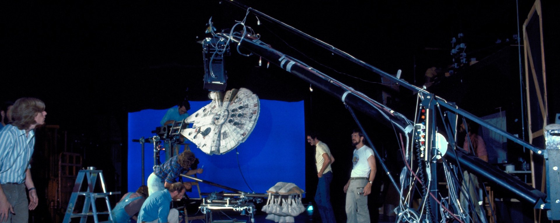
After some consideration of conventional bluescreen systems, we decided to innovate a little. First, we determined that we wanted a transmission screen, Steward (T matte). We used daylight-corrected, fluorescent tubes to facilitate movement of the screen and to optimize the screen’s efficiency. We converted their operation from AC to DC to eliminate possible flicker problems with real time or high-speed photography. This provided us with a portable backlit bluescreen, easily moved by two men to cover the format on extreme camera moves. This screen has approximately twice the output of a conventionally lit transmission bluescreen of the same size, draws the same amperage and is virtually “hot spot” free.
In addition, a rotoscope department was developed to work in conjunction with the optical department. Again, we found it necessary to construct the equipment ourselves. The rotoscope department not only provided garbage mattes and articulate rotoscope blob mattes, but also generated original images to be used for explosion enhancement, laser and flack effects.
With the bluescreen matting system, we still had to deal with the question of how to support the miniatures. Articulate rotoscope matting of the streaked images to remove a support proved incredibly difficult. To solve this problem, we constructed what we call a “blue pylon.” It consists of a central support tube containing electrical wiring as well as cooling air — the umbilical for the model. It is then wrapped with mercury-vapor neon which, in turn, is wrapped with acrylic plastic and coated with bluescreen material. The miniature is supported by this blue pylon. When the blue record is pulled to create the matte, the pylon completely matches the blue backing and eliminates the need for articulate rotoscope.
The department called “Control” has the responsibility of vaulting and routing each piece of film generated for this project. Control catalogues each piece of negative, and print, and their relationship to the 2 to 12 other pieces with which they will be combined in composite. Control has the responsibility of keeping infinitely accurate records and making film elements and information available on a moment's notice, a tremendous task considering the approximately 3,838 elements required for the 365 projected individual shots.
“The system can operate in a real-time mode for programming, but for rapid subject motion, the drive systems simply cannot move the camera at the speeds necessary for real time.”
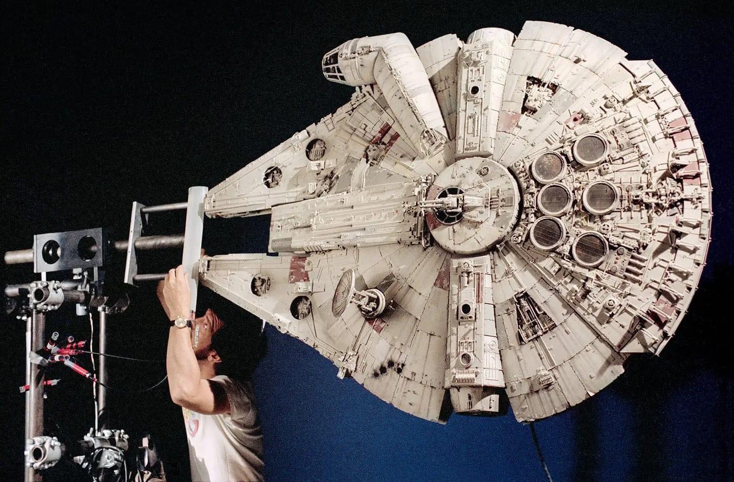
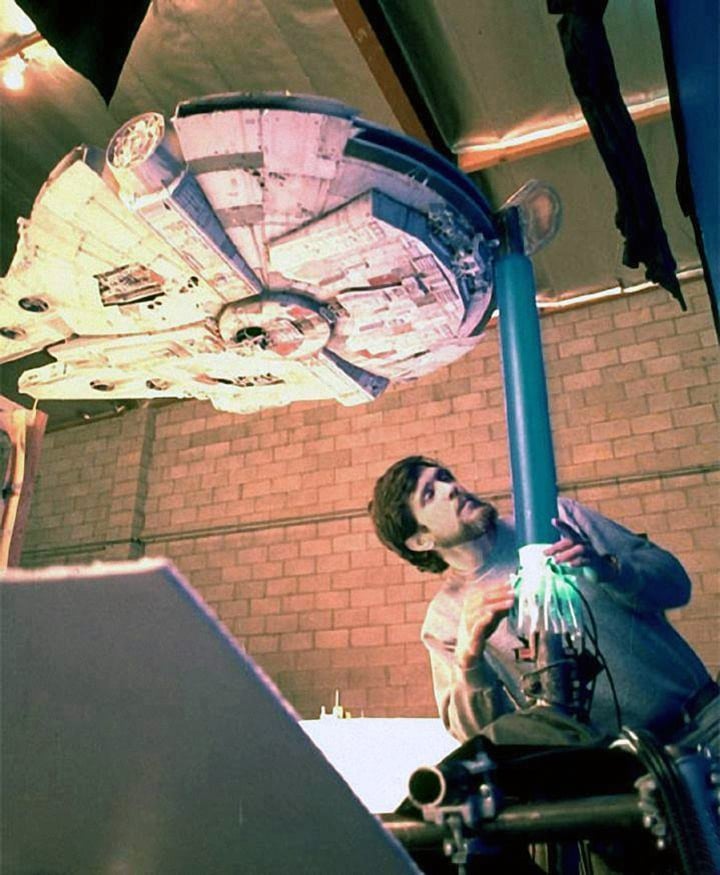
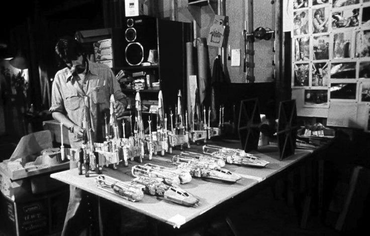
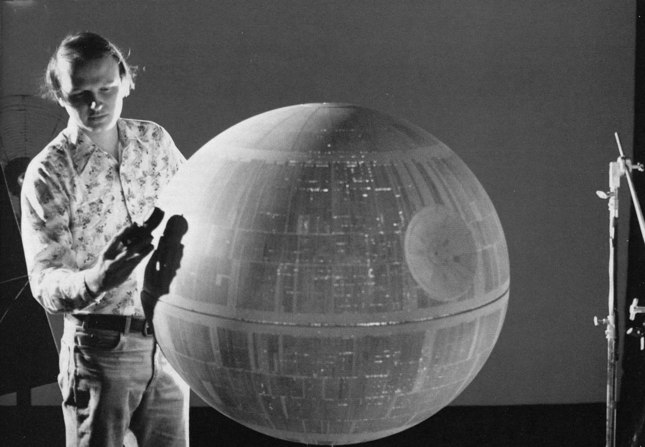
While all of the mechanical and electronic portions of the facility were being designed and constructed, one of the most important portions of the film was getting under way — the miniatures. Designs provided by Colin Cantwell were being modified to suit our photographic system and new designs for additional ships were being created. Joe Johnston had a major hand in providing the configurations that the final miniatures would incorporate. Grant McCune was assembling the people and facility needed to provide 75 models. Each of these models appear in several shots from a variety of camera angles. To accommodate this requirement, each specific design incorporated the ability to mount the miniature from the front, rear, top, bottom, and both sides. Each of the models included complex practical lighting for engine effects, laser weapon effects, and cockpit lighting. Some of the models had articulated details: wings that moved, rotating antennas, etc. All of the electrical leads for their motors and lights also had to be available at each of the mounting points. Because special high-wattage quartz bulbs were used in much of the practical lighting, cooling air was routed through the armatures of the miniatures.
The great number of miniatures which we would have to construct ranged from 1,600 square feet of highly detailed surface architecture of a mechanical planet called the Death Star, to tiny one-inch-high duplicates of the robots in the film, R2-D2 and C3PO. The scales of the miniatures had to suit the photographic methods used to record them. Edge detail had to be sharp but not too spindly because of the blue screen matting system. The size of each of the specific miniatures was determined by analyzing each shot projected for that miniature to appear in, and finding a scale that would satisfy depth of field, detail and size relative to other miniatures that had to appear with it in any given shot.
The color and paint detailing was given the same analysis and laid out with regard to the planets or other ships that a particular model was to appear over or with in a specific projected shot.
Many of the individual model designs needed to be duplicated several times for use in separate camera set-ups or shot showing tight formation. Also, duplicate ships were needed in shots which required a miniature to explode.
In view of the duplication necessary, we set about determining what methods would be best used to produce the individual pieces. We considered vacuum forming, injection molding, and silastic glove molds. Eventually we used all of these methods to speed miniature production. The parts for each duplicate ship were also produced in a variety of materials; foam with a surface coat was chosen for those ships which were to be exploded. Foam was chosen for this application because it is low-density and shatters easily. These characteristics were needed to make our explosion shots more realistic. The shattering nature of the foam allowed us to use much smaller, slower-burning explosive charge, and the low density of the pieces caused them to move more slowly, both contributing to the scale of the explosion.
With this brief and generalized description of each of our main areas, perhaps their interaction could most understandably be outlined by following an individual shot from conception to completion.
A TYPICAL SHOT
First, the motion, size, position in frame, and frame counts are determined by examining the black-and-white World War II dogfight footage. Our example will be a Mustang moving from left to right and away while we pan with him as he rolls and begins to dive. A Zero enters frame lower right in pursuit, firing its guns at the Mustang. Our camera position tracks with them as they both cross the horizon and move down toward the surface with the camera, platform/viewers point of view on their tails. This black-and-white footage is now translated into a storyboard drawing describing the actions of the WWII aircraft in terms of our miniatures. The Mustang will be replaced by an X-wing fighter, and the Zero will be replaced with a TIE fighter, firing lasers instead of bullets. The light sky in the black and white will become stars against black and the grey horizon in the black-and-white will become the Death Star surface.
The X-wing miniature is mounted from the nose mount so that it can roll about its own axis, yaw about its own axis, and crab to the side — in an axis perpendicular to the camera track motion. The camera, with its eyepiece mounted, is placed so that the ship is in the position indicated for the head of the shot.
Now the camera/subject motion programming begins. the dominant axis of motion is programmed first. In this case, the ship's motion away from camera and down in frame is established. With this portion of the program running, the "following pan" is put in. In this case, rotation of the ship on its vertical central axis will give the viewer a perspective change indicative of a pan, although the camera itself may not pan at all. With the crab and yaw motions on the ship running, and the track and tilt motions on the camera running, the ship's roll motion can be programmed to give the camera platform a feeling of motion.
All of the other motions of both camera and ship will be run while adding some roll to the camera, thereby giving the viewer the feeling that the camera platform is banking in order to follow the ship being photographed. These programming functions are being performed with the motion control system operating at approximately one-half real time — meaning that the motions seen through the eyepiece are at one-half the speed that those same motions will appear on the screen. The system can operate in a real-time mode for programming, but for rapid subject motion, the drive systems simply cannot move the camera at the speeds necessary for real time. I might add that even if the drive systems could operate that fast, it would be particularly dangerous, since if this shot were programmed in real time, it would require that the camera dolly and boom, move 40 feet from a standing start and come to a stop in just under six seconds.
Now that we have our move complete, the digital information (that is, the map of distances, accelerations, and speeds for that move), is transferred to a cassette for future use. We use frames-per-second as our increment of measure in the control system.
Example: The system running half real time is running on a 12-frame-per-second time base. We next reduce our time base from 12-frames-per-second to one-frame-per-second. This is really an exposure time of one-second-per-frame, but because pulldown of the film in this system is independent of exposure, the calculator automatically figures in the time required for pulldown, and compensates motion speed appropriately.
Because of this isolation of exposure and film advance and the long exposure times we are using to allow depth of field control, we have available shutter durations as long as 340. This long-duration shutter, though ideal for elimination strobing in extreme subject or camera displacement, must be used judiciously.
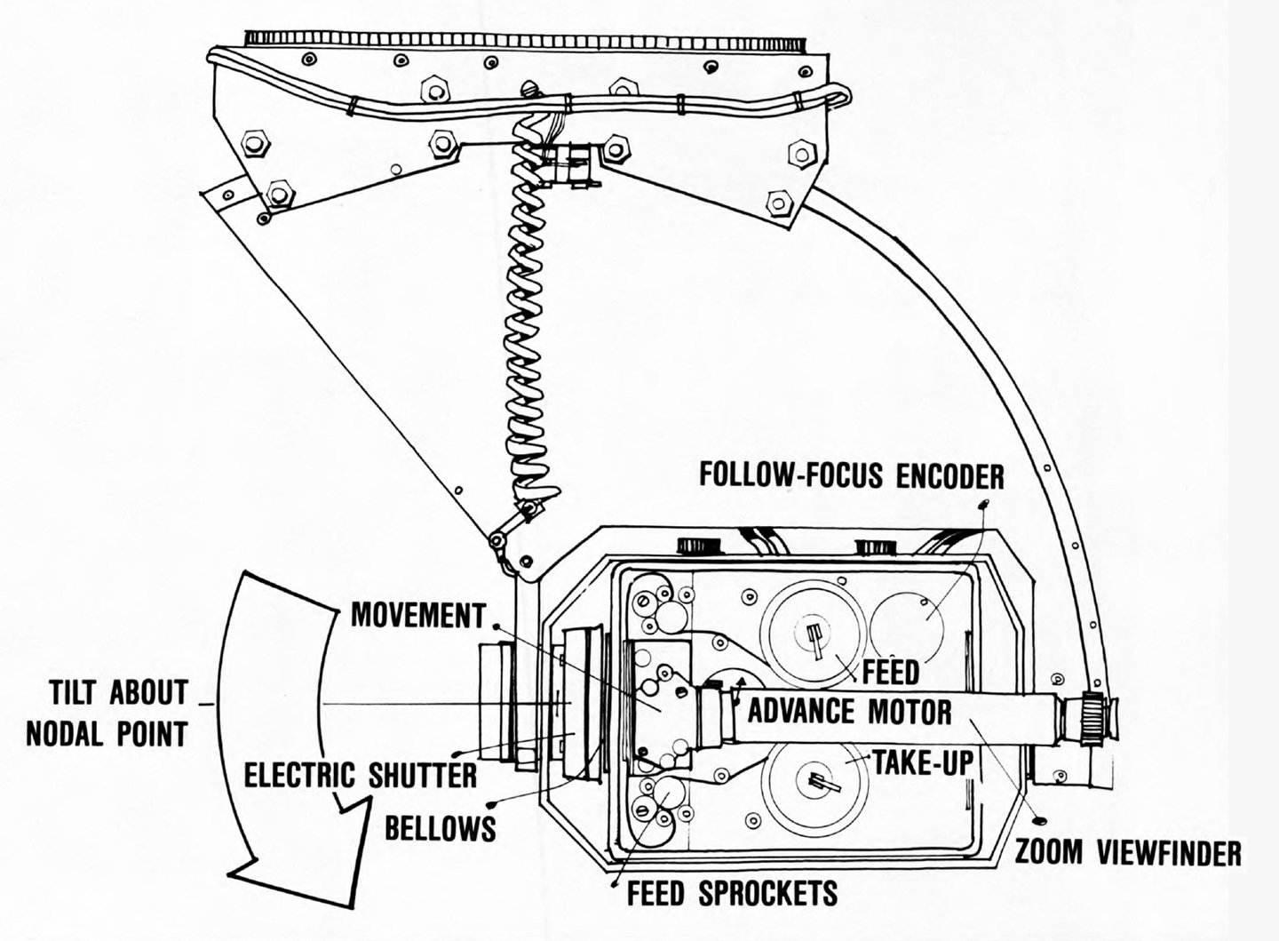
With our system, motion of camera and subject continues during exposure, just as in live-action photography. This is where the 300 shutter creates a problem. When the ship being photographed becomes small and its motion-per-frame is greater than a quarter of its overall size, it becomes a smear. In this situation, there is a happy medium of shutter-angle setting which makes the ship image apparently sharp and reduces strobing, minimizing that annoying syndrome as much as is possible. Once our shutter angle is chosen, we can deal with focus. The follow-focus device is built into the camera, and includes a tilting lens board for tailoring depth of field on tight shots. It runs off the same time base as the motion control motors. It can be initialized (establishing base point for focus calculations) and will change directly with the camera moves on the track. Or it can be individually programmed in cases where the camera subject distance is determined by something other than the camera track (if the camera boom is used or the subject is mounted on another track which moves it nearer to or farther from the camera during the shot).
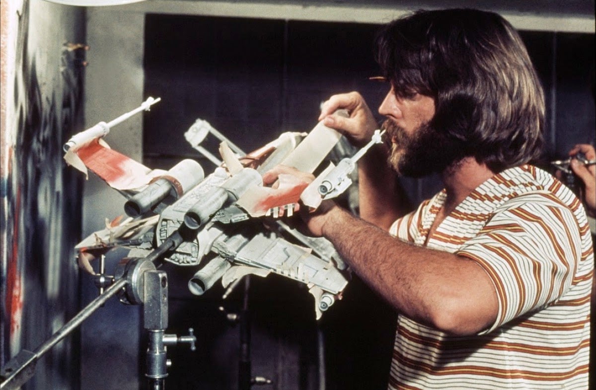
The blue backing is now covered to expose just the area around the X-wing. This is done to minimize blue reflections on the miniature. This leaves a lot of extraneous equipment in the shot: lamp stands, gobos, etc. These will be eliminated later by garbage mattes made in our rotoscope department. With the lighting set, focus and move programmed, we shoot this X-wing element on black and white negative material and process it in our black and white lab. This serves several purposes, it can be viewed immediately to check move, lighting, focus, etc. Its other purpose will be apparent later.
Because the X-wing is seen from the rear in this element, the photography on final color negative will be made in two passes — one to record the X-wing miniature with its key/fill light, and blue backing, and a second pass on a separate piece of negative to record the X-wing's engine light effect. The reason for this double pass is twofold. The built-in practical lighting, in this case the engines, is not bright enough to balance in exposure against the X-wing body and wings. The second pass allows us to increase the exposure and add some filtration to enhance the color and the flare of the engine light effect. Also, when using the blue screen matting system, it is very difficult to process a good fitting matte for the engine flare when the element must be matted over a grey value background. This double-pass approach on a complex move such as this is only possible because of our system's unique electronic and mechanical precision repetition of camera/subject position on a frame-to-frame basis.
We have now generated three pieces of film which exactly duplicate the motion of the X-wing miniature and its engine effects frame-by-frame. The black and white negative, which we have already processed, gives us a black X-wing image on a clear cell background. The color negative shows the X-wing and blue backing, and the third negative has the X-wing engine against a black field. A camera report is then made up for the processing of the color negative elements and set aside for delivery to the laboratory.
We now prepare the TIE ship miniature for photography. Normally, when one of the ships in a shot is firing lasers, the miniature has a laser emanation point provided in original photography. This point is usually a small light at the tip of the ship's laser cannon which lasts for one frame when a laser fires. In this case, however, the lasers are fired as the TIE ship is going away from the camera. Hence, no laser emanation point will be required on this shot. The TIE ship is mounted and we begin programming the second element of this shot. Because our camera platform, or viewer's frame of reference, is required to make some moves in this shot, we will use a portion of the program that we used to photograph the X-wing. We load the digital information off the storage cassette into solid-state memory in the control device, and we are ready to proceed. We are describing with the TIE ship basically the same move that the X-wing performed, but it will enter a frame later in the shot than the X-wing because it is to appear that the TIE ship is pursuing the X-wing. The only axes of motion that we must use from the previous program are the camera nodal point, roll, pitch, and yaw. This is necessary to maintain the camera platform/viewer frame of reference integrity. This motion will match the camera motion of the X-wing element on a frame-for-frame basis, so that no matter what position or independent motion we give the ship, the two shots will have the same angular displacement (nodal point camera motions) and, therefore, give the appearance that the camera platform/viewer frame of reference rotates and pans independent of the individual ship motions.
We will change the track motion, the crab motion, and the boom vertical motion slightly to give the TIE ship's move a subtly different character. We will move the track position in tighter to make the TIE ship larger. We will reposition the crab move to the left to have the TIE ship stay behind the X-wing and we will boom down to position the TIE ship higher in frame. The model crab, rotation, and yaw will remain the same to give the appearance of tracking the same moves that the X-wing is making. We now generate the same film elements on the TIE ship that we generated on the X-wing with the exception of the engine element. The TIE engine effect is provided by LEDs (Light Emitting Diodes), which record in the original key, and blue backing element photography.
First, we photograph the TIE ship move on the black-and-white negative material and process it. At this point we have another use for the black-and-white negative element which we made of the X-wing's move. We can "bi-pack" (lay together), the black-and-white negatives of the X-wing and the TIE ship in a registration viewer. Because the images of the ships are black, and the backgrounds are clear, we can see the motions of the ships relative to each other and the composition of the shot at projection speed. Having viewed this test, we can now modify the TIE ship move, if necessary, or go ahead and photograph the TIE ship move on color film.
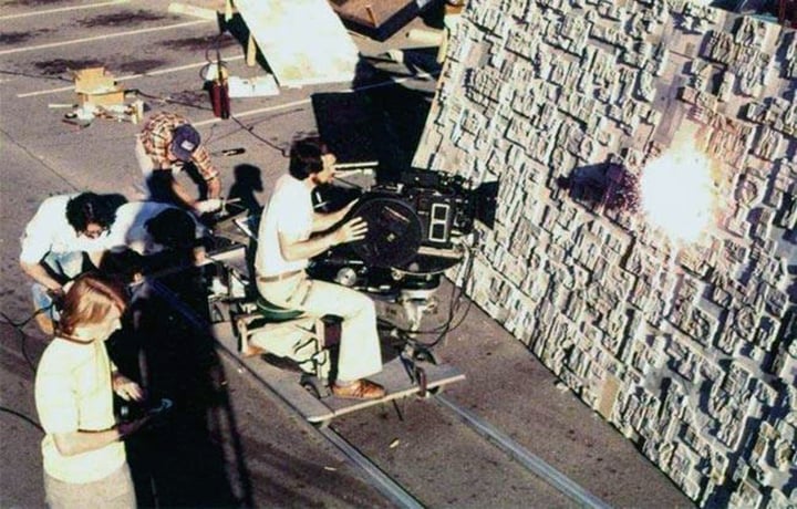
Once the TIE ship is photographed on color negative, we move on to the background in this case, stars and black sky — and the surface of our mechanical planet, the Death Star. This shot requires us to dive on the surface from high altitude in pursuit of the X-wing and TIE ship and pull out just above the surface. We have four scales of Death Star miniature to work with and, because of the extreme perspective change we have to go through to follow the X-wing and TIE ship realistically, we must use the second largest scale. This scale has the relief necessary to look realistic in the move, and is small enough in scale to provide the high-altitude to low-altitude diving portion of the shot without requiring a very great subject-to-camera distance in order to achieve the proper size change.
We can use the same camera nodal point, roll, pitch, and yaw that we used on the TIE and X-wing to provide that viewer frame of reference motion, but because this miniature is in a different scale than that of the X-wing and TIE ships, our linear track, crab, and boom moves will have to be reduced, not only in length, but in speed, as well. The linear moves will have to be programmed from scratch, so in order to make this program, we refer to the "bi-pack" black-and-white negatives of the X-wing, and TIE ship, that we used earlier to test the composition and speed of the two ships. By studying this presentation of the shot, we can then get an idea of what the background should look like. We program this move into the control system and shoot another black-and-white negative and process it. We can now tri-pack (triple thickness) the X-wing black-and-white negative, the TIE ship black-and-white negative, and the newly generated Death Star surface negative. Looking at this combination in the viewer tells us if the independent moves recorded on each of these pieces of film will sync together in a realistic-looking way. When we have a good-looking move, we then commit it to color negative. The Death Star surface we are using for this shot is too large to be placed in front of the blue screen. In order to make a matte to be used in optical to hold out the stars, we now make yet another digitally controlled move on the Death Star surface. But this time we front light the Death Star and overexpose the color negative a minimum of three stops. This provides us with a matte of the Death Star surface as a white, or clear cell, image against black. After the proper optical steps, the negative of that print will provide the optical element used to hold out the stars in our final composite. We now set aside the normally exposed image of the Death Star surface, and the overexposed image of the Death Star surface for delivery to the laboratory.
Finally, we prepare to photograph the stars for this composite shot on yet another piece of film. The Dykstraflex camera could be used to photograph the stars, but the star photography does not require the complexity of the ship and surface moves. Instead we will take the tape record of the camera nodel point roll, pitch and yaw to the Dykstraflex's sister camera and control system. This second system does not have the versatility of the Dykstraflex but exactly matches the motor speed per degree of angular motion of the Dykstraflex so that, by loading the digital information from the tape of the nodal point angular moves used on the surface, we can photograph the stars with an exactly matching set of angular moves. No track moves are necessary on the stars, as they are at an infinite distance and traveling toward them or away from them will not noticeably change their position in frame. Because no program changes were necessary in any of the axes, the star—move is photographed directly onto color negative and set aside for laboratory delivery.
The processed black-and-white negative of the X-wing, TIE ship and the Death Star surface, along with the tape of the digital information comprising those moves, are appropriately catalogued for future reference. The black-and-white negative will be used later for synchronization of all these elements, and the tape is held so that any element can be duplicated again should any harm befall the negative in its future travels, or should another shot require a similar move on a different miniature.
The negative with its latent images now becomes the responsibility of "Control". Control shepherds the film from that stage through all the steps that it must take from this point on to become a final composite. Control now sends the negative to the laboratory, ordering the appropriate prints for later use. In this case, each of the elements will be printed twice, with the exception of the X-wing engine effect, which will have a third, low contrast print made. This print will be used later in optical composite.
All of our prints are made at our specified printer light, and the laboratory graciously consented to run sensitometric color strips generated by us in order to allow control of the blue screen, and subject color. These strips were all shot at the same time and stored under ideal conditions until sent with our exposed negative.
This method allowed us to determine whether or not subtle color variations seen in daily projections were due to slight laboratory fluctuations or to some change in our system, such as aging lights or aberrations in the camera mechanics or electronics. We also ordered a quantity of print stock with a camera 1866 pitch and shape perforation. When contact-printed on a machine used for making internegatives, the print we received could be used for making rotoscope garbage mattes, and in some cases this print would actually be used in the optical printer as a printing element.
The morning following the photography on stage, we select takes in dailies. The individual takes may be different by design. One longer than another or perhaps a filtration variation. Shooting this variety helps expedite the completion of the shot should the pacing or visual nature of the shot require modification later.
The selected takes than appear via "control" at the viewer for synchronization. The viewer which we designed and built for our next step incorporates a pin-registered movement capable of projecting three thicknesses of our special 1866 printer stock, or six thicknesses of the mylar-base black-and-white negative stock. Because of the negative pitch stock and the pin-registration, this device can give a very accurate indication of matte fit and steadiness, even though the print we are viewing was continuos printed. The only variation that we generally find is a very slight bit of image weave. Using this machine, we now bi-pack the color print of the Death Star surface and its second-pass matte to make sure it fits. Now the color print of the stars is run against the matte of the Death Star to verify that the motions of the stars and surface match appropriately. We now check the X-wing color print against its second-pass engine effect to be certain of its matching up.
The black-and-white negatives of the X-wing, the TIE ship, and the surface that we generated during programming are now bi-packed with each of their color print counterparts to make sure that they are exactly the same. The reason for this last step is that the synchronization of each of these elements can be varied slightly (two or three frames) from what the original match up was at the time of photography. This slipping of synchronization can improve the feeling of the shot. The color print is a white or clear image of a ship against a black or dark blue background. When bi-packed, it is very difficult to see the ship, which falls behind or in front of the heavy density of the blue or black areas of the print. The black-and-white negative, with its black ship image on clear cell background, allows you to see all the ships, or surface relative to each other easily.
Once it has been determined that the black-and-white negative and the color print duplicate each other exactly, we set aside the color print, and run black-and-white elements in Bi-, Tri-, or Quadra-pack. When the composition, position, and speed of each element relative to each other element seems right, the elements are punched with a holepunch on a common frame. This sync punch is then transferred to the matching six color elements and sent back to control with specific instructions for "Optical," or "Rotoscope" regarding its optical combination.
The next step involves returning the color print elements to control with their sync marks and the instruction card. Control then records the key numbers from each piece of print and sends the prints with their instruction card to the optical department. The optical department attaches their own optical sync mark to color print elements and determines what pieces of film will have to be provided by rotoscope. In this shot, lasers firing from the TIE ship at the X-wing will have to be generated. The lasers will cause reflections on both the TIE ship that fires them and the X-wing which they will pass by. Because of the precision artwork this requires, optical may choose to make a registration print of these two elements. This print will more exactly match the position of the X-wing or the TIE ship on the original negative, than the continuos print. The blue screen elements of this shot will also need garbage mattes. With these—requirements determined, the appropriate elements will be sent to "rotoscope."
First, rotoscope will generate the garbage mattes. The TIE ship and the X-wing are the two elements that require garbage mattes for this particular shot. As you may remember, these two ships were shot against blue backing. To help reduce the blue-light reflections on the miniatures, we covered the majority of the blue screen. This left a small patch of blue around the miniature and a large black area that may have lamp stands or other equipment included in it. This black area with its attendant "garbage" is the reason for these garbage mattes. The rotoscope department will now put the color print of the X-wing in a device called a rotoscope camera which is capable of projection and photography through the same lens with the precision of a camera movement. The print will be projected frame-by-frame onto a surface with animation registration pegs. A cell is placed on this surface and a drawing is made which outlines all of the areas that we will not want seen in the final composite image. These drawings are blacked out in the areas to be eliminated. The drawings are then returned to the rotoscope camera where they are re-photographed off the same surface and animation pegs they were originally drawn on. This gives us a piece of film which will be used in conjunction with the X-wing element in the optical composite step to keep from printing the unwanted portion of the frame. A similar garbage matte is then generated for the TIE ship element.
With the garbage mattes complete, we will now move on to the laser beams and reflections. With the frame-by-frame drawing of each of the two ships, we can now establish their position relative to each other in any frame of the shot.
We discuss the choreography of the lasers and establish their speed and position. We also determine their number.
In this shot the TIE ship pursuing the X-wing fires a volley of lasers, starting on the 12th frame from the sync frame. These lasers miss, but some pass behind the X-wing, and some pass in front of the X-wing. To achieve this effect, two sets of lasers will have to be created—one set that passes over the X-wing and one set that passes behind the X-wing. The two sets are necessary so that when the optical department composites this shot, the set of lasers behind the X-wing can be covered up by the X-wing hold-out matte. Lasers typically last between three, and six frames. In this shot the volley which we mentioned will include seven lasers. These lasers will come from the TIE ship in a rapid fire fashion. The first laser fired will appear on frame 12, and the second on frame 14. The remaining five lasers will appear in two-to-four-frame intervals.
The interval and duration of the lasers provide us with the frames that we will have to be concerned with. In the same fashion that we generated the cells for the garbage mattes, we now generate a new set of frame-by-frame drawings. This set of drawings will include the positions of both the X-wing and the TIE ship on one cell. There is a cell for each of the frames which will include lasers. The first cell contains accurate drawings of the X-wing, and the TIE ship, as they will appear in frame 12 of the final composite.
The artwork for the laser is now created. This cell will have only the beginning of the first laser on it. The second cell contains the ships as they appear in the following frame (frame 13). The move that the ships make between this frame and the last is inspected and the artist creating the second frame of laser must compensate the position of this second frame of the first laser to allow for our apparent camera move.
Once the motion of the first laser is worked out, each of the successive lasers must be animated with regard to the laser that precedes it, and whether or not it passes in front of or behind the X-wing. With the laser portion of the animation complete, the reflections that those lasers create on the TIE ship which is firing them, and the X-wing which they are narrowly missing must be created. The laser beams are incredibly bright light sources. They illuminate those surfaces facing them, and cast shadows where their light is blocked from those facing surfaces. The artwork for these reflections take into consideration how many lasers appear in each frame and their distance and position relative to the ships.
We now have the artwork for the lasers, and reflections. This artwork will be photographed on five pieces of film: the color laser element which prints over the X-wing, and its matte, the color laser element which prints behind the X-wing, and its matte, and the color reflections which print over both the X-wing, and TIE ship. The front, and behind color laser elements are generated by photographing back-lit, hi-contrast laser artwork in two passes. The first pass is photographed with yellow filtration, and normal exposure. This provides the hot core of the laser. The film is rewound and a second exposure of the same artwork adds the green surrounding glow. This second exposure is made through a green filter, and a — diffusion filter. The diffusion provides the soft transparency of the laser's surrounding glow. Variations in exposure are also used to help make the lasers move away with a tracer-like character. This gives us the color laser elements to go in front of and behind the X-wing. Because of the laser's transparency and because they must be printed over the X-wing and Death Star surface, mattes must be made to keep the Death Star and the X-wing from exposing the negative in the areas in which the lasers appear in the final composite. This matte is made by photographing the laser artwork in exactly the same sequence on another piece of film which will be used to eliminate exposure in the areas on the negative where the lasers must expose. This gives us the lasers in front of the X-wing, the lasers behind the X-wing and their respective mattes. The last animation element to be generated consists of the reflections of the lasers on the ship. This element is photographed on color negative through a green filter and is to be double exposed or "burned in" during the optical composite step. It doesn't need to be seen in those areas of the ship which are lit by the key light so it needs no matte.
These elements are processed and printed for viewing the following day. Two prints are made from this color negative — one is our normal print and one is preflashed and slightly underexposed to reduce contrast. This second print will be used in the optical printer to produce the laser and reflection effects. It has this contrast reduction to compensate for the contrast increase inherent in the optical composite step. After viewing the normal print, and checking its synchronization against the rest of the elements in the shot, this material returns to optical via Control.
While rotoscope has been generating the lasers, reflections, and garbage mattes, optical has to be assembling the rest of the elements into one of their "optical blocks." A block consists of a group of shots that have similar printing requirements. This organization of material is incredibly complex. Paul Roth has the responsibility of overseeing the assembly of these elements in workprint form and then making certain that the original negative which was conformed (cut to match ) to the workprint is accurate.
This assembly of the elements is called "line-up." In our optical process there are two phases of line-up. The first phase orients the workprints of each of the pieces of film to one another by lining up their synchronization marks. These marks are the punches that we put on the film originally at the viewer.
We now have all the elements that we have generated for this shot parallel to one another with their sync frames all in a row. If we wind this film through a synchronizer we can see everyone one of the images that must appear in each frame of the final composite, now neatly lined up in a row.
With the shot lined up in this fashion it is spliced in sync onto rolls that include elements in parallel sync for another shot of similar complexity. When several shots have been assembled onto these rolls in this fashion, these rolls become an optical block.
This block will move through all the optical composite steps as a unit. The first place that the completed workprint optical block goes, is to the negative cutter via Control. The negative cutter conforms the original eight-perforation horizontal negative to the eight-perforation workprint. We now have the optical block rolls in eight-perf workprint, and eight-perf negative. Each roll of negative is now run against each roll of workprint to insure that they match to the frame.
Each of these rolls of negative is now used to generate the optical elements that will be used to composite the shot in its final form. The blue screen elements of the TIE ship and X-wing that we shot earlier will have separations made from them. The system we are using to make the mattes that isolate the ships from the background is called color difference.
Color difference is used because it is less time-consuming than bluescreen composites made by conventional, three-color separations and its matte techniques. The TIE ship and the X-wing separations are then used to create the hold-out matte and the window matte. These mattes will be used in the final composite step. Similar elements are generated on the Death Star surface and appropriate printing elements are made for the stars, all laser elements, the laser reflections, and the X-wing engines.
At this point, we have all the pieces of film that will have to pass through the printer to make the final composite. There are 28 pieces, not counting special garbage mattes, articulate rotoscope mattes, or the original negative from which these 28 printing elements were made.
The individual elements are distributed as follows: the TIE ship and the X-wing have four color printing elements, and four mattes each. The Death Star surface has five elements: three color printing elements and two mattes. The lasers over the X-wing, and under the X-wing have two elements each: one color, and one holdout matte. The X-wing engines, and the laser reflections are single color print pieces to be double-exposed and need no matte. And lastly, the stars do not print over any other image, which means that their color printing element needs no matte of its own.
Each of the color printing elements is used to produce an exposure on the final composite negative and each of the mattes is used to keep the composite negative from being exposed in an area that will receive exposure from another element.
The matte elements are usually used in pairs. The holdout matte is a black image of the subject to be matted in on that particular frame. This black image is surrounded by clear cell. This hold-out matte is used to keep the light used to expose the final composite negative from printing any information in the area that the subject of this holdout matte will occupy in the final composite. The other element of the pair is called the window matte. This matte is used to keep the material which is in the frame with the subject of the matte from printing. In our system this matte is usually a composite of the blue screen matte with its edge gradation and the garbage matte generated in rotoscope.
This composite matte gives us a totally black frame with a hole (or window) for the subject to print through. At this point we have matte pairs for the TIE ship, and X-wing, the surface, and each of the laser elements in the shot. The composite goes together much in the manner of a three-dimensional jigsaw puzzle. When we applied the sync marks to the elements at the viewer we also described which element crosses over which other element. The description which optical has for this shot is as follows:
• The TIE ship crosses over both sets of lasers, the X-wing, the Planet, and the Stars.
• The reflection element crosses over the TIE ship.
• The "over the X-wing lasers" cross over the X-wing, the Planet, and the Stars.
• The X-wing crosses over the "under the X-wing lasers," the Planet and the Stars.
• The reflection element crosses over the X-wing.
• The "under the X-wing lasers" cross over the Planet and Stars.
• The Planet crosses over the Stars.
This description determines the order in which the printing elements must be used.
Our optical printers are basically two projectors and a camera. In order to maintain the quality of our original negative through the various printing steps we combine all of our eight-perf horizontal elements through an anamorphic squeeze printing lens onto a four-perf vertical format (standard 2.40-to-1 Panavision release format). In this way, our image is only one dupe generation from the original photography.
I will describe the optical combination of this shot as simply as possible.
First we determine which image has the most other information matted over it. By starting with this piece we will use all of the holdouts of the images to be combined in this shot and remove each holdout as we prepare to insert the subject of that holdout. The holdout was providing an unexposed place on the composite negative. This will, hopefully, help to simplify the explanation, even though it may not exactly describe the way this shot will be composited. In this shot the element that has the greatest number of elements matted over it is the stars.
The stars must appear everywhere in the scene where there is no other subject. To achieve this we project the star element, (stars completely filling the negative area) onto the raw stock upon which the final composite will appear. In order to keep the stars from exposing in those areas of the composite negative where other images are to appear, we used the holdout mattes of all other elements in the shot. These mattes are put in registration with the star field we are projecting. (The hold-out matte being clear cell with a dense black image of the subject of that matte on it). The mattes of the surface, the lasers, the X-wing, and the TIE ship keep the star image from exposing the composite negative by blocking the light in the exact shape and position of these subjects. We now have the latent image of a star field with perfect holes for each of the other images to print into.
We next select the element that has the next greatest number of the remaining elements printed over it. In this case, that is the surface of the Death Star. That color printing element is now projected onto the composite negative just as the stars were. Before we expose the Death Star surface onto the four-perf composite negative, the hold-out matte of the Death Star surface is removed, and the window matte of the Death Star surface is combined with the holdouts of the lasers, the X-wing, and the TIE ship. The purpose of the Death Star window matte is to eliminate everything in the Death Star color printing element that we do not want to see (lights, stands, etc.). We print this combination, and now have on the composite negative the latent image of the stars and the Death Star surface, both with perfect holes for the remaining images to print into. Before continuing, we remove the window matte of the element we just printed, allowing additional images to be printed into those areas.
The step that we just performed is repeated on the laser element, the X-wing element, and the TIE ship element — each time removing the hold-out matte for the color printing element that we are exposing, and inserting the window matte for that color printing element. Having completed the exposure of all the color printing elements with their appropriate matte pairs, we now have a single four-perf anamorphic negative with all of the elements of our shot printed on it — each element occupying only the space allowed for it by its mattes, and each element printed over, and under its appropriate fellow elements to achieve the proper perspective.
The print back of our composite is viewed and corrections, if any, are made. Once the composite is accepted, a print goes to editorial, the negative goes to the negative cutter via the Control department.
That is the history of one of our shots, with an average level of complexity and difficulty. There are 364 more to be completed.
For their efforts, Dykstra, Edlund, McCune, Blalack and John Stears would go on to share the 1978 Academy Award for Best Visual Effects. Dykstra, Edlund and Muren were all later invited to join the ASC. You'll find AC's complete Star Wars archive here.
If you enjoy archival and retrospective articles on classic and influential films, you'll find more AC historical coverage here.
Access the every issue of AC and every story from more than the last 100 years with our Digital Edition + Archive subscription.